Calibration Parts
In this section, we will discuss the importance of printing the calibration parts included in the .3MF file before starting the full print of the TNY-360 robot.
We'll also see how to tweak the parameters of the 3D printed parts to adapt them to your specific printer and components.
Overview
If you open the TNY-360.3mf file with a compatible slicer software, you will find a first print plate named "CALIBRATION".
This print plate contains several calibration parts that are designed to help you test the fit of the screws and components that will be used in the assembly of the robot.
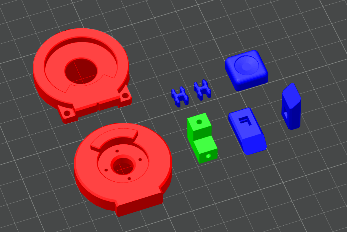
Here's a quick overview of the calibration parts you will find :
- Joint Assembly :
To test the fit of the round servo horns inside the leg joints, and ensure the two parts rotate smoothly without too much friction or play. - Screw hole :
To test the fit of the servo's screws in the holes of the printed parts, and ensure the holes are the correct size for a secure fit. - Clip system :
To test the fit of the clip system (used to hold the decorative parts in place), and check that the clips can snap in and out as intended.
The Joint Assembly
The joint assembly calibration part consists of two pieces that fit together to simulate the leg joints of the robot.
By printing this part and testing the fit of the servo horn inside the joint, you can ensure that the holes are the correct size and that the joint rotates smoothly without too much friction or play.
How to use
To assemble the joint calibration part, insert the round servo horn into the hole of the Joint-Outer piece, and then screw the 4 1.4mmx5mm screws through the holes of the horn to secure it in place.
Verification
The servo horn should fit snugly inside the hole, without any friction or play.
If the fit is too tight, you may need to slightly increase the hole compensation settings in your slicer, or manually adjust the servo horn size in the FreeCAD files before printing the entire robot.
The 4 holes of the servo horn should align with the holes of the Joint-Outer piece
If the holes do not align properly, you may need to adjust the hole positions in the FreeCAD files before printing the entire robot.
The screws should fit securely in the holes without stripping or cracking the plastic
If the screws do not fit properly, you may need to slightly adjust the hole compensation settings in your slicer, or manually adjust the screw hole size in the FreeCAD files before printing the entire robot.
Once the servo horn is installed, place the Joint-Inner piece on top of the Joint-Outer piece, and rotate them together to test the movement of the joint.
Verification
The parts should fit together smoothly, without any friction or play.
If there is too much friction, you may need to slightly increase the hole compensation settings in your slicer.
The joint should rotate smoothly without any binding or resistance.
If the joint does not rotate smoothly, you may need to slightly increase the hole compensation settings in your slicer. If there is play in the joint, you may need to slightly decrease it.
The joint should have a 180° range of motion without any interference.
If the joint does not have a full range of motion or has interference at certain angles, you may need to check your top layer ironing settings, or print slower to improve the precision of the walls.
Adjusting the servo horn size
To adjust the servo horn size in FreeCAD, open the Settings.FCStd file located at the /CAD folder.
Inside the Settings document, you will find a Global spreadsheet. This spreadsheet contains the key dimensions of the robot.
To adjust the size of the servo horn hole, you can modify the value next to the Servo Wheel Diameter cell. Increasing this value will make the hole larger, while decreasing it will make the hole smaller.
After adjusting the value, you will need to re-export some STL files for the leg joints, and then re-import them in the .3MF file to apply the changes to the calibration part and the entire robot :
- re-export the
Joint-Outerpart from theSettings.FCStdfile, and save it as an STL file. - Open the
Leg-Top.FCStdfile located in the/CAD/01_Partsfolder, and re-export theLegTop FR,LegTop BR,LegTop BLandLegTop FLparts as STL files. - Open the
Leg-Bottom.FCStdfile located in the/CAD/01_Partsfolder, and re-export theLegBottom LandLegBottom Rparts as STL files. - Finally, open the .3MF file in your slicer, and replace the old STL files with the new ones to apply the changes to the calibration part and the entire robot.
Adjusting the horn hole positions
To adjust the horn hole positions in FreeCAD, open the Leg-Top.FCStd file located in the /CAD/01_Parts folder.
Once opened, find the LegTop Base body, and modify the Sketch named Sketch003 (under the Pocket002 feature). Change the position of the holes in this sketch to adjust the hole positions for the servo horn.
After adjusting the hole positions, you will need to re-export the LegTop FR, LegTop BR, LegTop BL and LegTop FL parts as STL files, and then re-import them in the .3MF file to apply the changes to the calibration part and the entire robot.
You will also need to adjust the position of the holes in the Leg-Bottom.FCStd file, by opening the Leg Bottom R - Template body, and modifying the Sketch named Sketch003 (under the Pocket002 feature).
After adjusting the hole positions, you will need to re-export the LegBottom L and LegBottom R parts as STL files, and then re-import them in the .3MF file.
Adjusting the screw hole size
To adjust the screw hole size in FreeCAD, open the Leg-Top.FCStd file located in the /CAD/01_Parts folder.
Once opened, find the LegTop Base body, and modify the Sketch named Sketch003 (under the Pocket002 feature). Change the size of the holes in this sketch to adjust the hole positions for the servo horn.
After adjusting the hole positions, you will need to re-export the LegTop FR, LegTop BR, LegTop BL and LegTop FL parts as STL files, and then re-import them in the .3MF file to apply the changes to the calibration part and the entire robot.
You will also need to adjust the size of the holes in the Leg-Bottom.FCStd file, by opening the Leg Bottom R - Template body, and modifying the Sketch named Sketch003 (under the Pocket002 feature).
After adjusting the hole sizes, you will need to re-export the LegBottom L and LegBottom R parts as STL files, and then re-import them in the .3MF file.
The Screw Hole
The screw hole calibration part consists of a simple L-shaped piece with two holes in it.
It is designed to test the fit of the servomotor's screws, as well as the hole Z-compensation (because of teh overhang sagging).
How to use
Take one of the screws included with your servomotors, and try to screw it into the holes of the calibration part.
Verification
The holes should be circular
The top and side holes should be circular and not deformed. If the holes look like ovals, you may need to adjust the XY compensation settings in your slicer, or adjust the Side Hole Compensation settings in the FreeCAD files.
The screws should fit securely in the holes without too much force
The screws should fit snugly in the holes without forcing too much on them while screwing them in, or without stripping the plastic.
If the screws do not fit properly, you may need to slightly adjust the hole compensation settings in your slicer, or manually adjust the screw hole size in the FreeCAD files before printing the entire robot.
Adjusting the side hole compensation
To adjust the side hole compensation in FreeCAD, open the Settings.FCStd file located at the /CAD folder.
Inside the Settings document, you will find a Global spreadsheet. This spreadsheet contains the key dimensions of the robot.
To adjust the side hole compensation, you can modify the value next to the Side Hole Compensation cell. Increasing this value will make the holes bigger in the Z direction and smaller in the XY direction.
After adjusting the value, you will need to re-export the parts that contain holes for the servomotor's screws, for this :
- Re-export the
ServoScrewpart from theSettings.FCStdfile, and save it as an STL file. - Open the
Leg-Top.FCStdfile located in the/CAD/01_Partsfolder, and re-export theLegTop FR,LegTop BR,LegTop BLandLegTop FLparts as STL files. - Open the
Torso.FCStdfile located in the/CAD/01_Partsfolder, and re-export theTorso Bottompart as an STL file. - Finally, open the .3MF file in your slicer, and replace the old STL files with the new ones to apply the changes to the calibration part and the entire robot.
Adjusting the screw hole size
To adjust the screw hole size in FreeCAD, open the Settings.FCStd file located in the /CAD folder.
Inside the Settings document, you will find a Global spreadsheet. This spreadsheet contains the key dimensions of the robot.
To adjust the screw hole size, you can modify the value next to the 'Servo Screw Hole Radius cell (which is actually the Diameter and not the Radius). Increasing this value will make the holes bigger, while decreasing it will make the holes smaller.
After adjusting the value, you will need to re-export the parts that contain holes for the servomotor's screws, for this :
- Re-export the
ServoScrewpart from theSettings.FCStdfile, and save it as an STL file. - Open the
Leg-Top.FCStdfile located in the/CAD/01_Partsfolder, and re-export theLegTop FR,LegTop BR,LegTop BLandLegTop FLparts as STL files. - Open the
Torso.FCStdfile located in the/CAD/01_Partsfolder, and re-export theTorso Bottompart as an STL file. - Finally, open the .3MF file in your slicer, and replace the old STL files with the new ones to apply the changes to the calibration part and the entire robot.
The Clip System
The clip system calibration part consists of two plastic clips and two basic parts with holes for the clips to snap in, it also includes the Clip Tool part which is designed to help you install the clips without breaking them.
This calibration part is designed to test the fit of the clip system that is used to hold the decorative parts of the robot in place.
How to use
Take a clip and place it in the hole of the Clip Tool. Then, use the Clip Tool to insert the other end of the clip into the hole of one of the basic parts, and snap it in place.
Once the clip is installed, place the other basic part on top of the first one, and press them together to snap them together.
Verification
The clips should fit in the clip tool without any friction
The clips should fit snugly in the hole of the Clip Tool without any friction. If you have to force the clip into the hole, you may need to slightly increase the hole compensation settings in your slicer.
The clips should snap in the holes of the basic parts without too much force
The clips should snap in the holes of the basic parts without forcing too much on them. If you feel like you might break the clips while snapping them in,
you may need to slightly increase the hole compensation settings in your slicer or adjust the clip design in FreeCAD.
The clips should hold the parts together securely without any play
Once the clips are snapped in, they should hold the parts together securely without any play. If there is play between the parts (other than a slight rotation play due to plastic deformation),
you may need to slightly increase the hole compensation settings in your slicer or adjust the clip design in FreeCAD.
Adjusting the clip design
If the clips do not feel secure enough, or if they are too difficult to snap in, you can adjust the clip design in FreeCAD.
To do so, open the Master_Clip.FCStd file located in the /CAD/03_Common folder.
Once the file is open, you will see 3 Bodies :
- Clip :
This body contains the design of the clip itself. You can modify the shape and dimensions of the clip to make it easier to snap in, of make two parts fit together more securely. - Hole_Tool :
This body contains the volume of the holes that the clips snap into. You can modify the shape and dimensions of this part to make it easier to snap the clips in, or to make them fit more securely. - Clip_Tool :
This body contains the design of the Clip Tool, which is used to help you install the clips without breaking them. You can also modify the design of the Clip Tool if you want to (for example, making the tool bigger if you have big fingers).
If you modified the Clip body or the Hole_Tool body, you will need to re-export some STL files and re-import them in the .3MF file to apply the changes to the calibration part and the entire robot :
- Re-export the
Clippart from theMaster_Clip.FCStdfile, and save it as an STL file. - Open the
Leg-Top.FCStdfile located in the/CAD/01_Partsfolder, and re-export theLegTop FR,LegTop BR,LegTop BLandLegTop FLparts as STL files, as well as all the Decorative parts (Deco Bottom R,Deco Bottom L,Deco Top R,Logo R,Stripes R, etc.). - Open the
Leg-Bottom.FCStdfile located in the/CAD/01_Partsfolder, and re-export theLegBottom LandLegBottom Rparts as STL files, as well as all the Decorative parts (Cover R,Cover L,CoverBlack R,CoverBlack2 R, etc.). - Open the
Torso.FCStdfile located in the/CAD/01_Partsfolder, and re-export theTorso Bottom,Cover,Wing R,Wing LandLogopart as an STL file. - Finally, open the .3MF file in your slicer, and replace the old STL files with the new ones to apply the changes to the calibration part and the entire robot.